A tutorial on how to make an adjustable delay timer circuit using 555 IC that can automatically turn on/off any output after a fixed duration. This electronic timer circuit is helpful when you need to power On/Off any AC Appliances after a pre-defined duration. For example you can use this circuit to automatically turn Off a mobile charger, after let’s say 1 hour, to prevent overcharging the battery.
The timer delay can be fixed to time periods like 1, 5, 10 minutes etc. (or for any duration ranging from a few seconds to hours).
Do watch the video tutorial above for detailed step by step instructions on how to build this circuit and for visual demonstration of how this circuit works. (Both the scenarios viz. Auto turn Off and Auto turn On are included)
Components Required
Below is the list of components required for building the electronic delay timer circuit:
- 555 Timer IC
- Momentary Push Button Switch
- LED / any output device
- 470uF Capacitor
- Resistors: 68K, 10K, 220R
- Breadboard
- Few Breadboard Connectors
- (5-12)V Power Supply
- Potentiometer (Optional)
- Relay Module (Optional)
Refer to the LED resistor table shown in the video tutorial for the exact value of LED’s series resistor (220R)
Fixed Delay On Off Timer Circuit
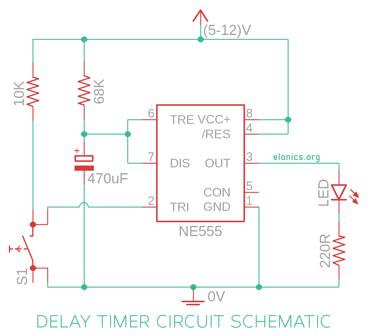
The below figure is the schematic of a simple automatic on off timer with a fixed timing resistor and capacitor. So the time period after which this circuit will automatically turn on/off the output is fixed and can be found out by using the formula mentioned in the calculation section.

In order to control AC Appliances or any heavy loads like DC motors using this circuit, you need to add a relay module at the output of the 555 timer IC (As shown in the video tutorial).
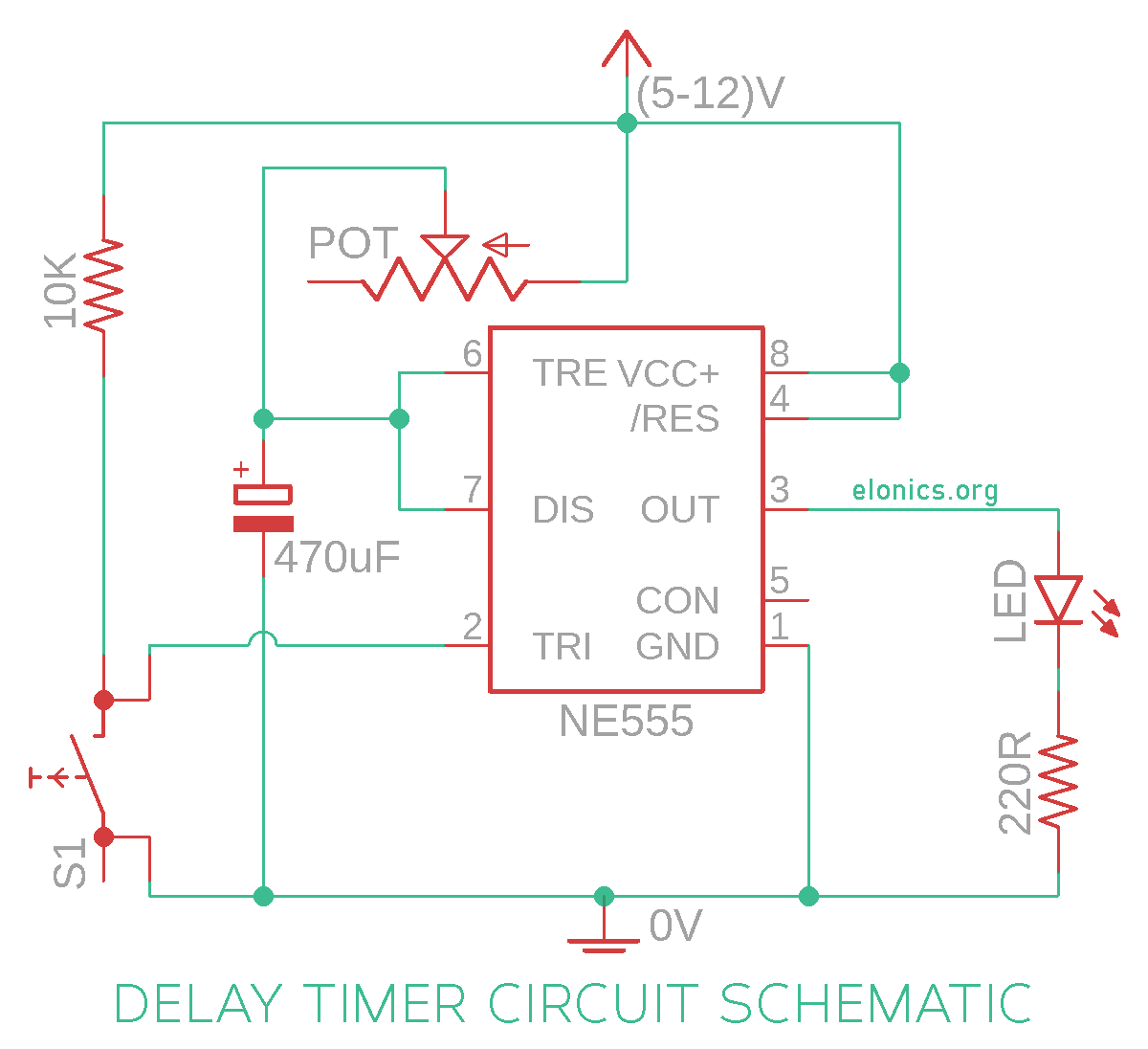
Adjustable Delay On Off Timer Circuit
For adjusting the timer duration on the fly, the timing resistor is replaced by the potentiometer and its connections are made as shown in the circuit diagram below. You can choose the potentiometer value depending on the maximum duration you require.

How This Circuit Works
In the previous tutorials of the 555 timer project series, we have learnt how the trigger pin (Pin2) and the threshold pin (Pin6) of the 555 timer IC sense voltages and control the output. Below is the recap:
- If the Trigger Pin (Pin-2 of the 555 timer IC) senses any voltage less than 1/3rds of the supply voltage, it turns ON the output
- If the Threshold Pin (Pin-6 of the 555 timer IC) senses any voltage more than 2/3rds of the supply voltage, it turns OFF the output
- Whenever the output of the 555 timer IC is in OFF state, the Discharge Pin (Pin-7) acts as ground/negative rail i.e, it is internally connected to 0V
Keeping the above 3 points in mind, lets try to understand how this circuit works.
Initially when this circuit is powered on, the output will be in OFF state. Whenever the output is OFF, the discharge pin (Pin 7) will be internally connected to 0V. So the capacitor completely discharges and won’t be able to charge via the series resistor that connects it to positive rail.
When the momentary push button switch is pressed i.e, the delay timer is activated, the following sequence happens:
- 0V is applied at the trigger pin (Pin-2) via the push button switch
- Since this applied voltage (0V) at Pin-2 is less than 1/3rd of the supply voltage, the output turns ON
- Simultaneously, the discharge Pin disconnects internally from 0V
- So now the capacitor starts charging via the resistor/potentiometer that connects it to positive rail
- Since the threshold input pin (Pin-6) is connected to positive terminal of the capacitor, it actively monitors the voltage across it
- As soon as the capacitor charges to 2/3rds of the supply voltage, Pin-6 turns OFF the output
- (This time period for which the capacitor charges from 0V to 2/3rds of supply voltage is the delay time)
- As soon as the output turns OFF, Pin-7 is internally re-connected to 0V and the capacitor is discharged completely
- The above steps are repeated each time the push button switch is pressed
Turning ON the output means that the voltage at the output pin (Pin-3) of 555 timer is at Vs (Supply Voltage). Output being in OFF state means the voltage is at 0V.
In the video tutorial, I have connected anode of the Blue LED to the output of 555 timer IC and the cathode to negative rail. For the Red LED, I’ve connected it’s cathode to the output of 555 timer IC and the anode to positive rail. So when the output of 555 timer is in ON state, the Blue LED glows and when the output turns OFF, the Red LED glows.
Calculating Delay Period of the Timer
The time period of the delay timer circuit we made is equal to the time taken by the capacitor to charge from 0V to 2/3rd of the supply voltage, and theoretically the value is equal to:
T = 1.1 * R * C, where T is the time period in seconds and R, C are the values of timing resistor and capacitor used.
For example, in the circuit diagram of the fixed delay duration timer, we have used a 68K resistor and 470uF capacitor which gives us a delay time of:
T = 1.1 * (68000) * (0.000470) = 32 seconds.
And to calculate the component values for a given delay time, it is easier to fix the value of capacitor and calculate the resistor value. For example, if we require a delay time of 60 seconds:
60 = 1.1 * R * (0.000470). On solving this equation, we get the value of R to be 116K.
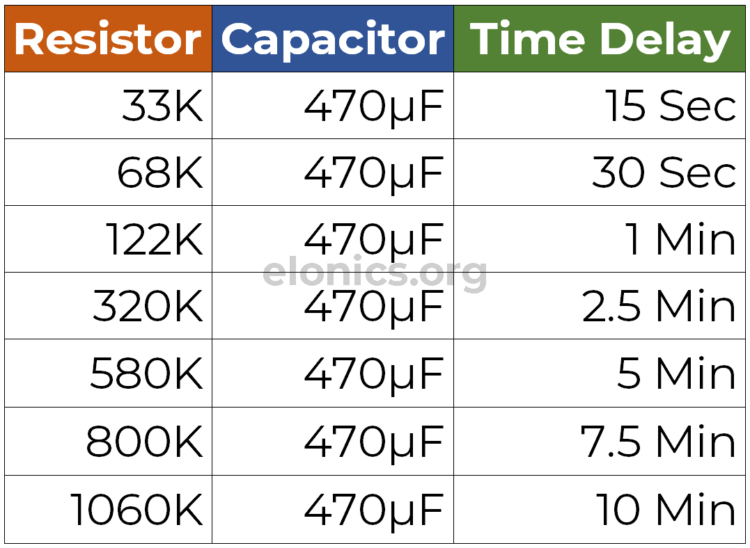
Practically, the delay time will be higher than the calculated value because of leakage of the capacitor. So for your reference, I have measured and tabulated the values of timing resistor and capacitor for basic intervals, in the image below.

Applications
- For automatically turning Off mobile chargers to prevent overcharging the battery
- To turn Off reading lights automatically after the set duration
- To control sequence of output devices one after the other after regular/irregular time periods (This can be achieved by cascading multiple delay timer circuits via the reset pin of 555 timer IC)
- In Auto power On/Off circuits using Relays
If you have any queries/suggestions, feel free to post them in the comments section of this video: Adjustable Auto On Off Delay Timer Circuit Using 555 IC
