A tutorial on how to make an Adjustable Flashing/Blinking LED circuit using 555 timer IC and a few other electronic components. This circuit toggles an LED or any output device ON and OFF at regular intervals of time. The duration between successive toggling of LED can be adjusted by using a potentiometer.
Watch the video above for detailed step by step instructions on how to build this circuit. Explanation of how the circuit works is also included in the video.
Components Required
- 555 Timer IC
- LED or any output device
- 10uF Capacitor
- Resistors: 100K, 1K, 220R
- Breadboard
- Few Breadboard Connectors
- (5-12)V Power Supply
- Potentiometer (Optional)
- Relay Module (Optional)
Refer to the resistor table shown in the video tutorial for determining exact value of LED’s series resistor (220R)
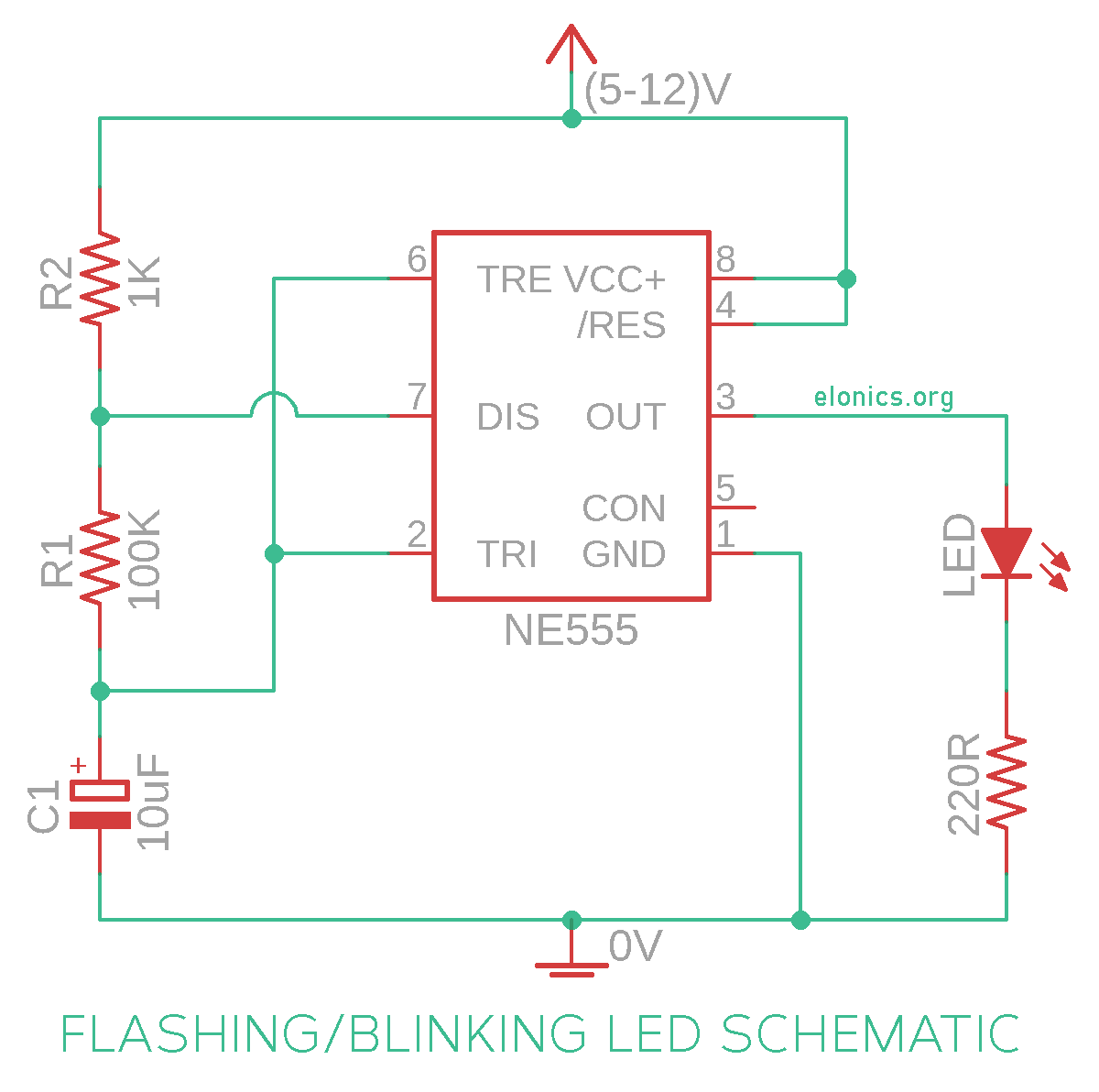
Circuit Diagram
The resistors R1 and R2, along with the capacitor C1 control the blinking rate. While capacitor C1 and resistor R1 influence both On and Off times of the LED, Resistor R2 is responsible only for the On time. So if you want to try out different resistor values and change the flashing rate, you can experiment by changing the value of resistor R2.

[The value of series resistor connected to the LED depends on two parameters: the color of LED you are planning to use and the voltage of power supply. You can find the corresponding values in the video tutorial]
Below is the circuit diagram of adjustable dual LED flasher that uses a potentiometer to modify the blinking speed:

Notice how we connected an extra LED to the output pin of 555 timer IC. This arrangement allows only 1 LED to stay ON at any given time, which causes this circuit to function as an alternating LED flasher.
How This Circuit Works
[Do watch the video tutorial provided at the beginning of this tutorial for better visual understanding]
In the previous tutorials of the 555 timer project series, we have learnt how the trigger pin (Pin2) and the threshold pin (Pin6) of the 555 timer IC sense voltages and control the output. Below is the recap:
- If the Trigger Pin (Pin-2 of the 555 timer IC) senses any voltage less than 1/3rds of the supply voltage, it turns ON the output
- If the Threshold Pin (Pin-6 of the 555 timer IC) senses any voltage more than 2/3rds of the supply voltage, it turns OFF the output
- Whenever the output of the 555 timer IC is in OFF state, the Discharge Pin (Pin-7) acts as ground/negative rail i.e, it is internally connected to 0V
Keeping the above 3 points in mind, lets try to understand how this circuit works.
- Immediately after the power supply is turned on, the capacitor (C1) will be in discharged state and so the voltage at Pin-2 will be 0V.
- Since this voltage is less than 1/3rds of the supply voltage, the output turns ON.
- Simultaneously Pin-7 will internally disconnect from 0V and so the capacitor starts charging via resistors R1 & R2.
- Immediately after the voltage across capacitor (C1) crosses 2/3rds of the supply voltage, Pin-6 senses it and turns OFF the output.
- Simultaneously Pin-7 will reconnect internally to 0V, which results in capacitor discharging via resistor R1.
- And once the voltage across the capacitor falls below 1/3rd of the supply voltage, Pin-2 will turn ON the output and this whole cycle repeats again and again. (The sequence continues from the 3rd step)
You can practically observe this charging and discharging of the capacitor by measuring the voltage across it using a multi-meter.
Further Improvements
We have configured the 555 timer IC to operate as an astable multivibrator. So the output will be an alternating square wave which causes the LED to instantly turn ON or OFF.
We can modify this circuit to produce a sine wave so that the toggling between ON and OFF states are visually smooth (Similar to a fading effect). It can be done by adding an extra transistor and driving it from the voltage at positive terminal of the capacitor. We will discuss more about this in another tutorial.
Applications
- In turning indicator circuits of all types of vehicles and cycles
- In Strobe lights / SoS signalling circuits (To signal that someone is in danger or needs help)
- To control wiper motors and create to and fro motion
- In Light indicators used in cars (The relay version of the flashing LED circuit is used)
- As an input for applications that require timing pulses. E.g: In counter circuits using 4017 & 4026 ICs
If you have any queries/suggestions, feel free to post them in the comments section of this video: Adjustable Flashing/Blinking LED Circuit using 555 Timer IC
