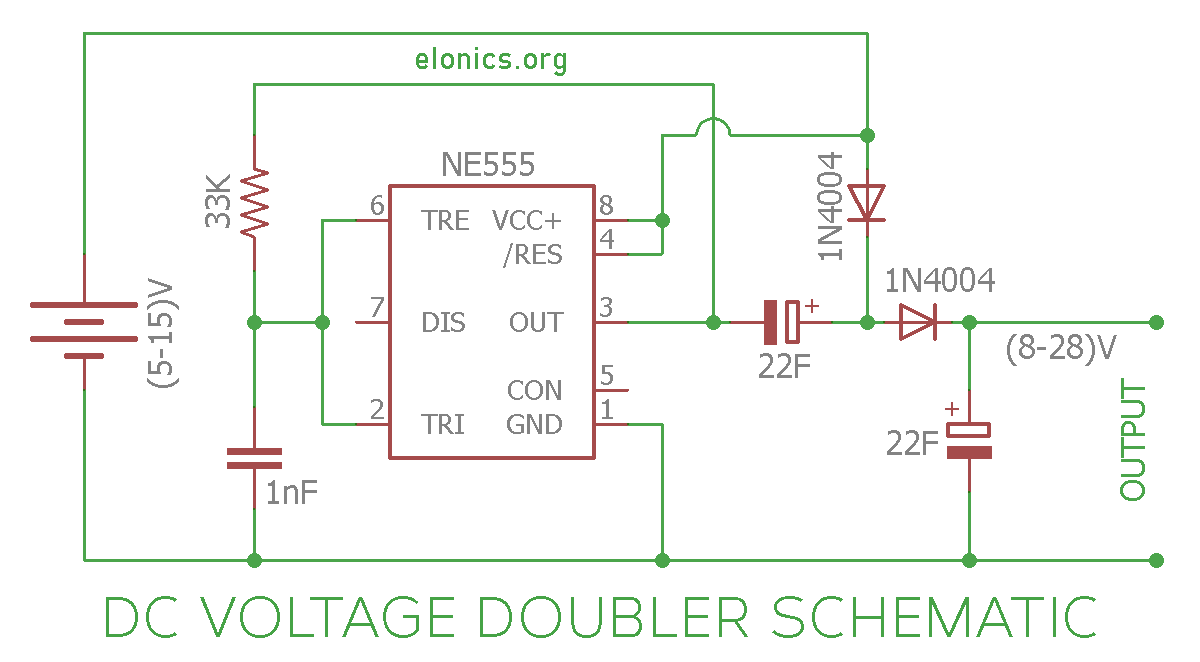
A tutorial on How to make a DC Voltage Doubler Circuit on breadboard using 555 Timer, Diodes & Capacitors. This circuit takes in a DC voltage anywhere between 5V to 15V and produces double the input voltage at the output. For example if the input voltage is 12V, the voltage at the output of this circuit will be approximately 24V.
Explanation of how this circuit works is also included in this article.
Components Required
- 555 Timer IC
- Diodes: 2 x (1N4004 / 1N4148)
- Capacitors: 2 x 22uF, 1 x 1nF (Labelled as 102 or 0.001uF)
- 33K Resistor
- Breadboard
- Few Breadboard Connectors
- (5-15)V Power Supply
Circuit Diagram

Construction & Working of the Circuit
Terms & Concepts used in this explanation:
- Positive rail is the (+) of the power supply. Likewise Negative rail is the (-) or 0V of the power supply.
- A diode allows current to flow only in one direction. More specifically, it allows current to flow only when when the voltage at the p-terminal of the diode is more than that at the n-terminal by a certain value (named as bias-voltage ~ 0.7V)
The 555 timer IC, in combination with the 1nF capacitor and 33K resistor, produces a square wave at its output i.e. at Pin-3. A square wave means that the signal alternates between positive voltage and negative voltage continuously. For example if the input power supply is 6V, the voltage at the output of 555 timer IC will be at 0V for sometime, then change and stay at 6V for sometime, change back to 0V and so on.
Now we added a 22uF capacitor with its negative terminal connected to the output of 555 timer IC and its positive terminal connected to the positive rail via a diode. The logic behind this arrangement is this:
When the output of 555 timer IC is at 0V (negative voltage), the 22uF capacitor charges through the diode. The voltage to which this capacitor gets charged is equal to the supply voltage mins the forward bias voltage of the diode, which approximately is equal to the positive voltage of the power supply.
When the output of 555 timer IC is at positive voltage, the voltage across the 22uF capacitor will be in series with the voltage from the output of 555 timer IC.
Since two voltage sources in series will add up, the voltage at the other end of 22uF capacitor will be equal to voltage at the output of 555 timer IC + the voltage across the capacitor. And since the voltage at the output of 555 timer IC as well as the voltage across the 22uF capacitor is equal to the positive voltage of power supply, the final voltage will be double the input voltage. Also, because the voltage at n-junction of the diode is more than that at the p-junction, no current flows back to positive supply rail.
So by now we have a voltage that is approximately double the input voltage. Another p-n diode is added to prevent the current from flowing back to the capacitor from the output load. At the end a 22uF capacitor is connected to smoothen out the output.
The above capacitors and diodes arrangements is named as a capacitor charge pump.
Further Improvements
We can cascade the diode-capacitor arrangement at the output of 555 timer IC to generate much higher voltages. The resulting circuit is called as a voltage multiplier circuit. It outputs a certain times input voltage as output voltage. The factor by which the output voltage is more than the input voltage is determined by the number of stages of capacitor+diode charge pump blocks used.
I’ll make another tutorial on this soon. Stay tuned.
Applications
- Voltage Doublers are used in microwave ovens where voltages of the order of thousands are required and the use of transformers is not practical.
- they are used for generating voltages that generate strong electric fields in cathode-ray tubes
- In circuits powered by low voltage sources
If you have any queries/suggestions, feel free to post them in the comments section of this video: DC Voltage Doubler Circuit Using 555 Timer IC
