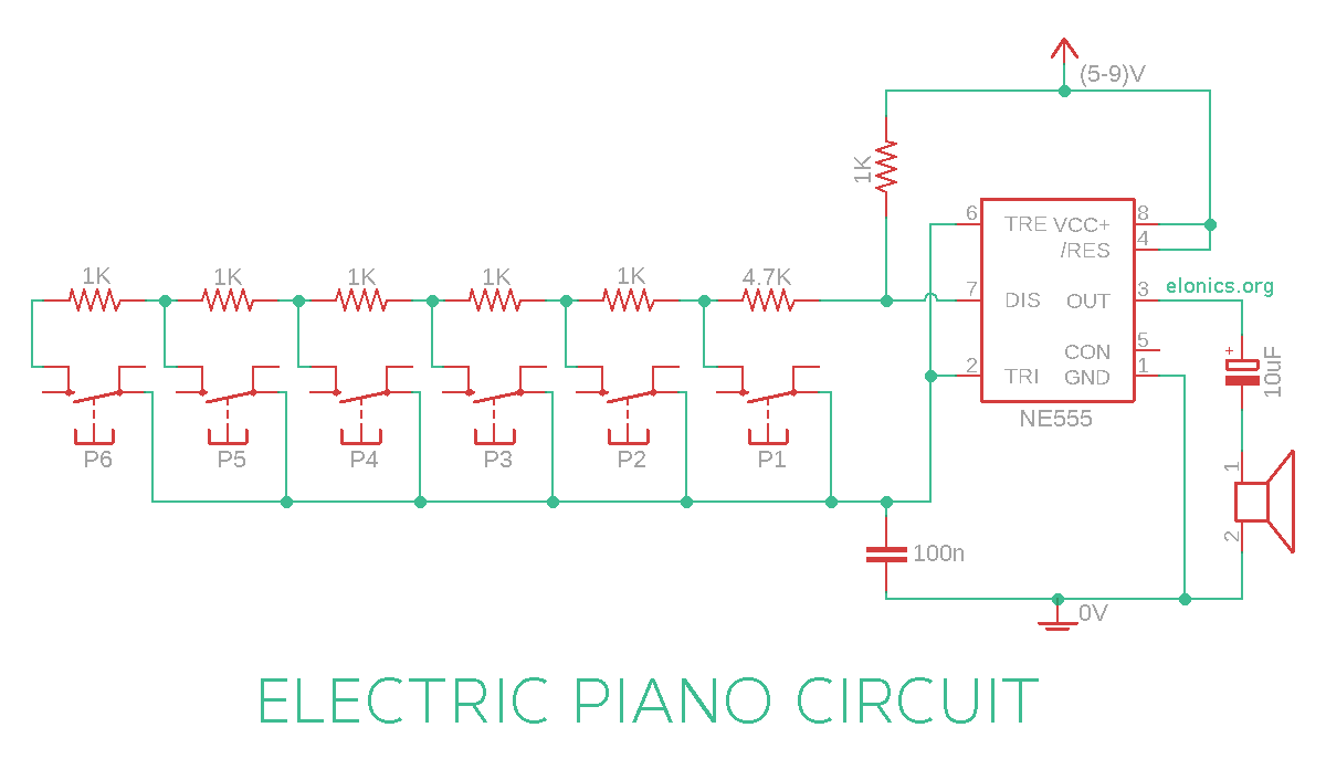
A tutorial on how to make an Electronic Piano circuit using 555 timer IC and a few other electronics components. This circuit consists of a number of push button switches (similar to different keys in a piano) which, when pressed, produce sounds with different tones via a speaker.
The frequency of the output tones can also be fine tuned by calculating the precise values of resistors to use. Formula for calculating the frequency is included in the explanation section of this tutorial.
Watch the video above for detailed step by step instructions on how to build this circuit. Explanation of how the circuit works is also included in the video.
Components Required
- 555 Timer IC
- 8 Ohm Speaker
- 6 x Momentary Push Button Switches
- Capacitors: 100nF, 10uF
- Resistors: 6 x 1K, 4.7K
- Breadboard
- Few Breadboard Connectors
- (5-9)V Power Supply
Circuit Diagram
[Click on the image for a full resolution picture]

How This Circuit Works
In one of the previous tutorial (Adjustable Flashing/Blinking LED Circuit using 555 Timer IC) we have learnt how changing the value of resistor in series with the capacitor changes the flashing rate (Frequency). And the relation is of inverse proportionality i.e, if the value of resistance in series to the capacitor is large, the frequency will be less, and vice versa. You may refer to that tutorial for better understanding of how the values of resistors and capacitor influence the output frequency.
Formula for calculating the frequency of the output sound/tone:
Frequency (f) = 1.44 / ( (R1 + 2 * R2) x C1 )
In the circuit we made, the value of R1 is 1K and C1 is 100n. After replacing these values in the above formula, we have:
Frequency (f) = 1.44 / ( (1000 + 2 * R2) x 10-7 )
We can also rearrange the formula to calculate the value of resistor we need to use for any frequency required:
Resistance (R2) = ( ( 1.44 x 10⁷ ) / f ) - 500
If you have any queries/suggestions, feel free to post them in the comments section of this video: DIY Electric Piano Circuit using 555 timer IC
