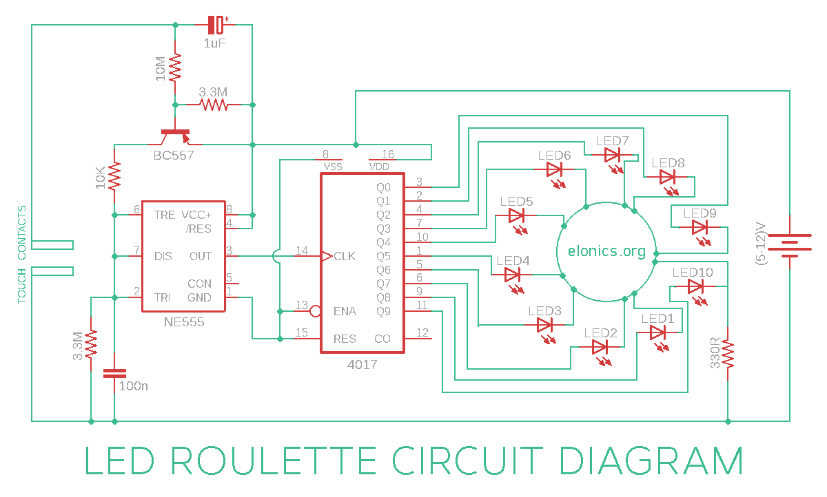
A tutorial on how to make an LED roulette circuit using 555 timer & 4017 IC on a breadboard. This circuit replicates the functioning of circular roulette wheel. Circuit diagram, detailed steps to build this circuit and an explanation of its working is also included.
The roulette wheel consists of certain numbers arranged circularly and each person who plays the game has to bet a certain amount against any number he/she chooses. One person need to touch a pair of touch contacts provided at the left side of circuit. Then the LED’s rotate for some time and come to halt at a random number. The persons who bet money on the number at which the LED stops will get all the amount that has been bet by everyone who played that particular game.
To learn more about roulette wheel game, click here.
Components Required
- 555 Timer IC
- 4017 IC
- PNP Transistor (I used BC557)
- 10 LED’s
- Resistors: 330R, 10K, 2 x 3.3M, 10M
- Capacitors: 1uF, 100n
- Breadboard
- Few Breadboard Connectors
- (5-12)V Power Supply
Circuit Diagram

Click on the circuit diagram for full resolution image.
How This Circuit Works
Watch the video above, for better understanding on how this LED roulette circuit works.
Terms Used: Negative rail corresponds to 0V and Positive rail corresponds to the voltage of power supply used.
When you touch both the touch-contacts:
The 1uF capacitor charges because of current flowing through finger. When a capacitor charges, the voltage at its positive terminal approaches the voltage of positive rail, and the voltage at its negative terminal approaches the voltage of negative rail. And since the negative terminal of capacitor is connected to the base of transistor via a 10M resistor, the voltage at the base of transistor will be more towards negative rail.
The transistor is of pnp type. So if the voltage at its base is more towards negative, the transistor gets biased and starts conducting current between its emitter & collector pins. Otherwise no current flows between them. So more the negative voltage at the base of transistor, more will be the conductivity between its emitter & collector pins.
One terminal of 100n capacitor near the 555 timer IC is connected to negative rail and the other is connected to positive rail via a 10K resistor & transistor. And the speed with which this 100n capacitor can charge or discharge determines the frequency of output square wave from 555 timer IC. Since the conductivity of transistor increases, the 100n capacitor will be able to charge quickly and so the frequency of output wave from 555 timer IC increases.
The output of 555 timer IC is connected to the clock input of 4017 IC. Also the speed of rotation of the LED’s is directly proportional to the frequency of clock input signal of 4017, which is the same as frequency of output wave from 555 timer IC. So the LED’s start rotating faster.
When we remove finger from touch-contacts:
The 1uF capacitor discharges slowly, so the conductivity between emitter & collector of transistor decreases, so 100nF capacitor takes more and more time for it to charge. So the frequency of output from 555 timer IC increases and as a result, the speed of rotation of the LED’s reduce and finally they come to a halt. (Since frequency of wave at the clock input of 4017 IC is same as frequency of output wave from 555 timer IC)
Further Improvements
This LED roulette circuit can also be used as an LED dice. To use only 6 LED’s instead of 10, you can disable outputs 7,8,9,10 outputs of 4017 IC by connecting its 7th output of 4017 IC to its reset pin via a 10K resistor. So the moment the 7th output turns on, it resets the IC and the output switches back to 1st LED.
Applications
- In electronic gaming circuits
- As a random number generator
- In touch intuitive decorative lighting setups
If you have any queries/suggestions, feel free to post them in the comments section of this video: LED Roulette Circuit using 555 Timer & 4017 IC
