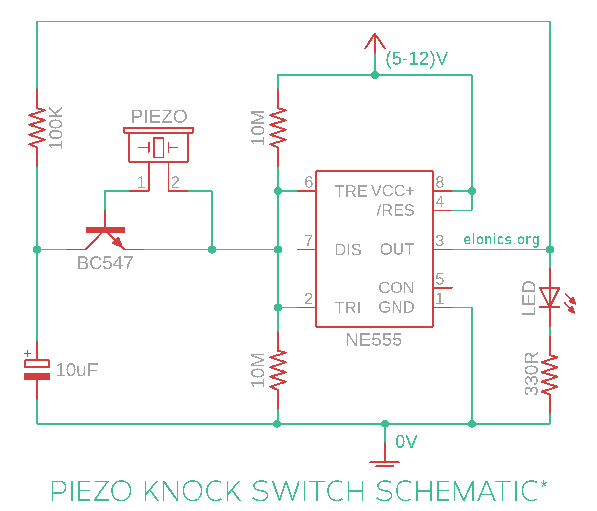
A tutorial on how to make a Tap On Tap Off piezoelectric knock sensor circuit using 555 timer IC on a breadboard. This circuit toggles (flip-flops) the output each time we tap on the Piezo-Electric speaker. So each time we tap/knock on the piezo speaker, the output turns Off if it is already in On state, and turns On if it is in Off state.
Watch the video above for detailed step by step instructions on how to build this circuit. Explanation of how the circuit works is also included in the video.
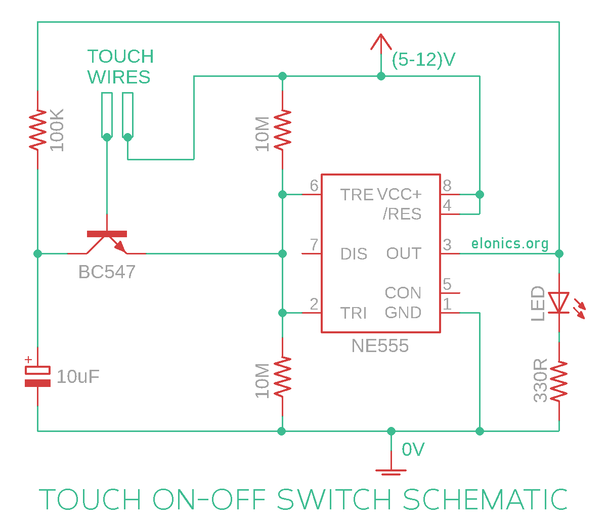
The principles that we used for designing this Piezo-Electric knock sensor circuit can also be used to make a touch on-off circuit by adding just a single pair of touch contacts. More information on this is at the end of video tutorial and in the circuit diagram section.
Components Required
- 555 Timer IC
- NPN Transistor (I used BC547)
- Piezo Buzzer
- LED / Any Output Device
- Resistors 1 x 100K, 2 x 10M, 1 x (The series resistor for LED, refer to the video tutorial for its value)
- 10uF Capacitor
- Breadboard
- Few Breadboard Connectors
- (5-12)V Power Supply
Circuit Diagram

You can just replace the piezoelectric speaker with two pairs of touch contacts in order to make a latching touch On-Off sensor switch circuit. Below is the circuit diagram of that arrangement:

How This Circuit Works
[Watch the video at the beginning of this post for better visual understanding of the explanation]
A Brief Recap: In the previous Project - Touch On-Off Sensor Switch Circuit Using 555 Timer IC, we learnt that if Pin-2 (Trigger Pin) of 555 IC detects a voltage less than 1/3rds of supply voltage, it turns ON the output & if Pin-6 (Threshold Pin) detects a voltage more than 2/3rds of supply voltage, it turns OFF the output. We used this concept to turn the output ON & OFF with just a touch of our finger. And in this project: Latching Touch Sensitive Alarm Circuit Using 555 Timer IC, we tried to latch the output by creating a feedback mechanism with the help of an npn transistor.
For this project, the action (stimulus) that should cause the change in output is the tap/knock on the piezo sensor. Since the same action causes the output to turn On as well as turn OFF, we connected both Pins 2 & 6 to each other (Pin-2 is responsible for turning On the output and Pin-6 for turning it Off).
So now, by just controlling the voltage at the common point between Pins 2 & 6 of the 555 IC, we will be able control the output and toggle it to On or Off. On either side of this common point, a 10M resistor is connected to keep the voltage at half the supply voltage during idle time. This makes sure that stray electrostatic charges do not trigger the circuit unnecessarily.
The npn transistor along with the 100K resistor help in forming a feedback loop and flip-flop/toggle the output each time it is activated. In other words, if the output is On and the transistor is activated, it applies a positive voltage at the common point between pins 2 & 6. Pin-6 detects this and turns Off the output. Now the output is Off and if the transistor is activated again, it applies a negative voltage at the common point between pins 2 & 6. Pin-2 detects this and turns On the output. This is repeated again and again.
The transistor is triggered by the tap/knock on the piezoelectric speaker in the case of knock sensor circuit and via touch in the case of latching touch switch circuit. The 10uF capacitor helps in preventing multiple triggers of the transistor by deactivating the transistor for about 1-2 seconds after each tap on the piezo sensor.
Further Improvements
- Another transistor can be cascaded to the existing npn transistor to increase the tap/knock detection sensitivity
- Can be used as a simple door knock sensor (by removing the feedback loop). The idea is that the doorbell automatically rings when someone knocks on the door
- By connecting the output of 555 timer IC to the clock input of a 7-segment counter IC, we can create a footfall counter system. It can display the number of people who walked on the Piezoelectric sensor
Applications
- In earthquake detectors (The analog output of Piezo speaker is used)
- In automatic doorbell systems
- Used as a replacement for modern concealed switch systems (One just need to tap on a particular area to turn an appliance On)
If you have any queries/suggestions, feel free to post them in the comments section of this video: Piezo Electric Knock On-Off Sensor Switch Circuit Using 555 Timer IC
