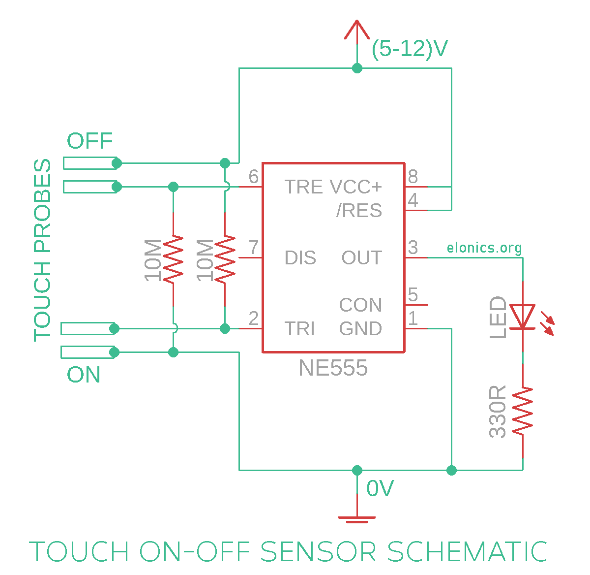
A tutorial on how to make a Touch On and Touch Off sensor switch using 555 timer IC on a breadboard. This circuit uses two pairs of touch conductors to sense and register the touch. One pair of touch conductors (sensors) for turning ON the output and the other pair for turning OFF the output.
You can use any output device like DC motors or AC appliances (like lights or fans) by using a relay at the output of 555 timer IC and by wiring the output device to the relay.
Do watch the video above for step by step instructions on how to build this circuit, and for understanding how this touch sensor circuit works.
Components Required
- 555 Timer IC
- 1 or 2 LED’s (You can also connect buzzers etc.)
- Resistors 2 x 10M, 2 x (The series resistor for LED’s)
- Breadboard
- Few Breadboard Connectors
- (5-12)V Power Supply
Circuit Diagram

Note: The value of series resistor connected to the LED depends on the color of LED you are planning to use and the voltage of power supply. You can find the corresponding values in the video
How This Circuit Works
[Watch the explanation part in the video at the beginning of this tutorial for better visual understanding]
The 555 timer IC has two sensing pins and one output pin. The sensing pins are Pins 2 & 6 (named as Trigger Pin and Threshold Pin) and the output is Pin-3.
The internal architecture of the 555 timer IC is such that, whenever Pin-2 (Trigger Pin) senses a voltage less than 1/3rds of supply voltage, it turns ON the output. Similarly when Pin-6 (Threshold Pin) senses a voltage greater than 2/3rds of supply voltage, it turns OFF the output.
For example, if the supply voltage is 9V, 1/3rds of it is 3V and 2/3rds of it is 6V. So if the trigger pin senses a voltage less than 3V, it turns ON the output & similarly if the threshold pin detects a voltage more than 6V, it turns OFF the output.
In the circuit diagram shown above, Pins 2 & 6 are connected via 10M resistors to the opposite polarities of what affects them, to keep the output stable. Since Pin-6 changes the output if it sees more voltage, it is connected to 0V through 10M resistor by default. Similarly is with Pin-2 to prevent unnecessary triggers by static charges.
So Whenever someone touches the contacts at Pin-2 and 0V, since Pin-2 senses ~0V because of current flowing though finger, it turns ON the output. And when we touch the contacts at Pin-6 and +ve Voltage, since Pin-6 senses ~+ve Voltage (which is more than 2/3rds of supply voltage), it turns OFF the output. Also the influence of 10M resistor is negligible when we touch the contacts with our finger, since the resistance at the finger will be much lesser.
And in this manner you can continue turning ON and OFF the output with just a touch of your finger!!
Further Improvements
- You can convert this circuit to Push ON Push Off circuit by just replacing the two pairs of touch contacts with two Push Button Switches
- Instead of using this circuit to turn ON only a single output, you can use two outputs ex: two LED’s and toggle between them when you touch either of the touch sensor contacts [The demo is included in the video tutorial]
Applications
- This touch ON touch OFF switch circuit, after adding a relay to its output, can be used to replace physical ON-OFF switches that we use in our homes
- Multiple circuits can be cascaded to make a security system, where the output turns ON only when a certain pre-defined combination of touches are made on the available touch contacts
- As a better ergonomic replacement for Momentary Push Button Switch
If you have any queries/suggestions, feel free to post them in the comments section of this video: Touch On-Off Sensor Switch Circuit Using 555 Timer IC
