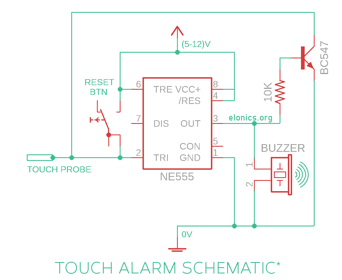
A tutorial on how to make a touch sensor alarm circuit using 555 timer IC on a breadboard. It consists of a touch sensor (made up of conductive material like copper wire) which when touched by our skin or any object with electric charge, activates the buzzer alarm connected at the output of 555 timer IC. Because of the latching mechanism integrated in this circuit, the output alarm stays ON continuously until the reset button is pressed.
Do watch the video tutorial above for step by step instructions on how to build this circuit, and for understanding how this touch sensitive alarm circuit works.
Components Required
- 555 Timer IC
- NPN Transistor (I used BC547)
- Buzzer
- LED (Optional)
- Momentary Push Button Switch
- Resistors 1 x 10K, 1 x (The series resistor for LED)
- Breadboard
- Few Breadboard Connectors
- (5-12)V Power Supply
Circuit Diagram

How This Circuit Works
[Watch the video at the beginning of this post for better visual understanding of the explanation]
A Brief Recap: In the previous Project - Touch On-Off Sensor Switch Circuit Using 555 Timer IC, we learnt that if Pin-2 (Trigger Pin) detects a voltage less than 1/3rds of supply voltage, it turns ON the output & if Pin-6 (Threshold Pin) detects a voltage more than 2/3rds of supply voltage, it turns OFF the output. We used this concept to turn the output ON & OFF with just a touch of our finger.
In this circuit, we need the output (buzzer/alarm) to be OFF by default. In other words, whenever we power on the circuit or press the reset button, the buzzer shouldn’t be turned ON. So we connected Pin-6 to positive rail, so that it always sees a voltage more than 2/3rds of supply voltage and keeps the output in OFF state (Until Pin-2 detects something!!).
For detecting the touch of out skin/finger, we used a conducting wire (labelled as Touch Probe in the circuit diagram). We connected it to Pin-2 of of the 555 timer IC so that whenever our skin comes in contact with the touch probe, it acts as a ground (-ve voltage) causing Pin-2 to detect a voltage less than 1/3rds of supply voltage. Because of this Pin-2 turns ON the output (The buzzer rings for a moment).
Immediately after the skin gets out of contact with the touch probe, pin-2 senses nothing and so the output turns OFF. In order to keep the output latched, even after the finger is removed from the touch probe, Pin-2 must sense less than 1/3rd of supply voltage. In order to do that, we used a transistor to invert the output signal and pass it to Pin-2.
So now immediately after Pin-2 senses a contact with the touch probe, it turns ON the output momentarily. This activates the transistor and it in turn applies 0V at Pin-2, thus keeping the output continuously in ON state (Now the buzzer rings continuously).
To reset the circuit i.e. to turn OFF the alarm/buzzer, we need to apply a +ve voltage at Pin-2. And pressing the momentary push button switch exactly does that.
Further Improvements
- A metal door knob can be used in place of touch probe in order to turn on an alarm whenever someone tries to open/touch the door knob
- Can be re-purposed as a simple touch detector circuit by removing the feedback loop and adding a smoothing capacitor at Pin-2
Applications
- In burglar detection systems that are based on changes in static charges
- In capacitive touch detection circuits
- As a replacement for momentary push button switch (The same circuit without the transistor and feedback loop)
If you have any queries/suggestions, feel free to post them in the comments section of this video: Latching Touch Sensitive Alarm Circuit Using 555 Timer IC
